Synthesizer Programming 1

Synthesizer Programming 1

SubTractor is a synthesizer that uses the classic technique known as subtractive synthesis. It generates sound using synthetic waveforms — that is, waveforms constructed from formulas. The waveforms feed into one or more filters to shape the sound. A typical thing to do is to generate a very bright waveform and then use filters to “subtract” parts of the frequency spectrum.

This way of synthesizing sound is among the earliest techniques used to make electronic music. It gained prominence in the electronic music studios of Cologne, Germany in the 1950’s and was developed further in the commercially produced synthesizers of the 60’s and 70’s (Moog, Buchla, ARP, EMS, etc.).

The basic idea is to use an oscillator to generate an audio signal, which oscillates “up” and “down” to mimic electronically the behavior of an acoustic sound pressure wave. The oscillator takes a single cycle of a waveform and then uses that to produce a continuous signal at any frequency you request. The filters affecting the oscillator sound reduce, or in some cases reinforce, parts of the frequency spectrum.

But this describes a static situation: the oscillator produces an unchanging, rather sterile sound, and the filter shapes that in some way that is also unchanging. The real interest in synthesis is to find ways to change dynamically many different aspects of the sound at the same time. A simple example is vibrato, which causes the pitch of the oscillator to wiggle up and down slightly, in order to sound more like a real acoustic instrument. There are many other ways to change the sound, some of which we will explore.

Explore Oscillators

Discover the sounds that oscillators can make.

  1. Create a Reason song file with one SubTractor.
  2. Begin with an Init Patch for SubTractor: click anywhere on SubTractor and choose Reset Device from the Edit menu.
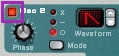
  3. When you play a note, Oscillator 1 generates a sound using a single cycle of a waveform. There are many types of waveform, including the traditional sawtooth, square, triangle and sine. You choose a waveform by clicking on the Waveform readout and dragging, or by using the adjacent up/down arrows.

    SubTractor oscillator waveform selection

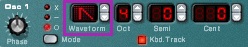
    The shapes represent the waveform types given above. There are 28 other waveforms, identified by number. Listen to them all to hear how they differ, but return to the first waveform: sawtooth.

  4. SubTractor oscillator 2 on/off switch

    You can enliven the static sound of one oscillator by mixing it with another oscillator. Enable Oscillator 2 by clicking on the Osc2 On/Off button.

    Both oscillators have a set of buttons that let you adjust their pitch, relative to whatever note you’re playing. The buttons adjust octave, semitone, and fine tuning. The latter lets you tune a pitch up or down by as much as 50 cents. (There are 100 cents in a semitone.)

    SubTractor oscillator tuning controls

    There are two simple strategies for tuning oscillators to make a more complex sound.

    • Tune the second oscillator so as to make a musical interval with the first oscillator, using the semitone and octave buttons. For example, tune the second oscillator up 7 semitones (perfect fifth).
    • Tune the second oscillator up by a very small amount, using the cent buttons, so that the two oscillator pitches differ by only a few cents. This is called detuning the oscillators. Then the two oscillators will “beat” against each other, which makes for a more lively sound.

      (Fun fact: The rate of beating is the difference between the two frequencies. For example, if one is 400 Hz and the other is 405 Hz, they will beat 5 times per second. Unfortunately, Reason doesn’t tell you what frequency in Hertz an oscillator produces.)

    DO THIS: Your patch should have both oscillators set to a sawtooth waveform, with the oscillators tuned according to either of the strategies given above.

Adjust the Amplitude Envelope

  1. Next, let’s shape the amplitude (or loudness) of the note, using an envelope generator. Right now, the patch behaves like an organ: fast attack, fast release. Let’s give it a slow attack and a slow release, like a gong.

    But first, some background. Reason uses the traditional ADSR envelope. That stands for “Attack, Decay, Sustain, Release” — the names of the four stages of the envelope. It’s important to understand what initiates each stage of an envelope.

    • Attack — begins when you press a key on the keyboard
    • Decay — begins when the Attack stage ends
    • Sustain — begins when the Decay stage ends
    • Release — begins when you release the key and continues until the note is silent.

    The settings you make for Attack, Decay and Release are times. The setting for Sustain is a level — how strong the note is after the Decay stage has elapsed, but before you release the note.

    ADSR envelope graph

    Note that if the sustain level is set to the maximum, then the decay time is irrelevant.

    SubTractor amplitute envelope ADSR sliders

    To set an envelope with a slow attack and a slow release, raise the A and R sliders of SubTractor’s Amp Envelope to a position that is halfway up or greater.

    DO THIS: Your patch should have an amplitude envelope with a slow attack and a slow release.

Filter the Oscillators

  1. A filter shapes the color of a sound by boosting or cutting the intensities of the various frequency components of the sound. SubTractor has two filters, and Filter 1 lets you choose several different types of filter. We’ll work with the Low-Pass (LP) type. A low-pass filter lets the lower frequencies pass unchanged, while it attenuates (reduces the strength of) the higher frequencies. In general, it makes sounds seem warmer; it takes the edge off of bright, buzzy sounds. Here is a frequency response graph that shows the effect of a low-pass filter.

    Low-pass filter frequency response graph

    Frequency is on the X axis; intensity (think “volume”) is on the Y axis. When a point on the graph is at 0 dB, there is no attenuation of the frequency at that point. Positive dB values represent a boost of intensity; negative values represent a cut, or reduction, in intensity. The cutoff frequency is the place where the filter begins to attenuate a region of the frequency spectrum. For a low-pass filter, the higher the cut-off frequency, the brighter the sound. As the cutoff frequency moves lower, more frequencies are attenuated, making for a darker, mellower sound.

    SubTractor filter cut-off frequency slider

    Play around with the Freq slider for Filter 1, which controls the cutoff frequency of a low-pass filter.

    Try some of the other types of filter by clicking the Type button.

    The types are:

    SubTractor filter type selector

    • LP 12 — low-pass filter with moderate slope (12 dB per octave)
    • LP 24 — low-pass filter with steeper slope (24 dB per octave)
    • HP 12 — high-pass filter (the opposite of a low-pass filter: lets the high frequencies pass)
    • BP 12 — band-pass filter: attenuates frequencies on either side of a bell curve centered around the filter frequency (the center frequency)
    • Notch — the opposite of a band-pass filter: attenuates frequencies only within the bell curve

    We’ll discuss these other types of filter later in the course. For now, just play around with them.

    Note that to use a low-pass filter effectively, the sound you filter must have some higher frequencies. Otherwise, you won’t hear much difference when you change the cutoff frequency. That’s why we have the oscillators producing a sawtooth waveform, which has a lot of high-frequency energy — lots of frequencies for a low-pass filter to attenuate.

  2. Many synthesizers let you set the resonance of a filter. The greater the resonance, the more pronounced is the effect of the filter. Specifically, for a low-pass filter, resonance produces a peak in the filter response just below the cutoff frequency.

    Low-pass filter frequency response graph with resonance peak

    SubTractor filter resonance slider

    Use the Res slider to explore the effect resonance has on the sound of the LP 24 filter.

Control the Filter with the Modulation Wheel

  1. It’s fun to turn the knobs and get different sounds, but what if you want to “turn the knobs” with a MIDI controller and record these motions into a sequencer? The simplest way is to set up the modulation wheel (controller number 1 — produced on our Triton Le by pushing the joystick away from you) to vary some aspect of the sound. SubTractor lets you control several things using the modulation wheel on the keyboard, among them the cutoff frequency of the filter. As it happens, the Init Patch is already set up to do this. If you’re using a low-pass filter, and the filter Freq slider is not all the way up, then moving the mod. wheel should change the brightness of the sound a little.

    We refer to the modulation wheel in this case as a control source, and the filter cutoff frequency as a destination. We use the stream of numbers emitted by the source to control the destination parameter. A destination parameter always has an initial offset: for the cutoff frequency parameter, this is adjusted using the Freq slider in the Filter 1 section. The variation applied by the control source is relative to the offset. So in our example, moving the mod. wheel up from its lowest (zero) position raises the cutoff frequency above whatever offset is specified using the Freq slider. So if that slider is already all the way up, the mod. wheel will have no effect.

    SubTractor modulation wheel control governing amount going to filter frequency

    The mod. wheel can be set to move the cutoff frequency either above or below the offset by a certain maximum amount. You change this using the F. Freq knob near the mod. wheel: a negative value moves the cutoff frequency below the offset; a positive value moves it above the offset. If this knob is in the center position (with the red light off), then moving the mod. wheel will have no effect on the cutoff frequency.

    Turn the F. Freq knob all the way to the right (maximum positive amount). If you set the filter’s cutoff frequency (Freq slider) to the lowest value, then moving the mod. wheel up (JS+Y on the Triton) will raise the cutoff frequency. Try it.

    DO THIS: Your patch should have a low-pass filter, with a very low cutoff frequency and a moderate amount of resonance. Also, the mod. wheel hould be configured to raise the cutoff frequency when you move up the mod. wheel.